


Safety precautons
- ● At the start of operation, check to see if the product operates normally.
- ● We advise the customer to take fail-safe or safety measures against possible damages which may be caused by a failure of the product.
- ● We do not guarantee the performance and functionality of the product if it is used under conditions other than those set forth
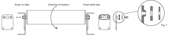
in the specification or in any modified form. - ● The product is intended to rotate in a predetermined direction. Prior to use, please confirm the direction indicated on the side face of
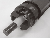
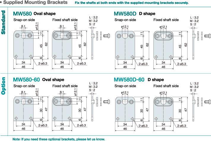
the product. - ● Please fix the supplied brackets on both end shafts tightly (see Fig. 1).
- ● In order to avoid damage to the internal mechanism, be careful not to drop the product or give it a shock.
Before use
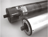
2-1 Mounting the product on your conveyor frame
● Securely fix the product with the supplied mounting brackets.
● Avoid installing the product in any of the following places where:
- the product may be exposed to direct sunlight;
- the product may be directly subject to vibration or shock;
- the ambient temperature is not within -5 to 40°C;
- the ambient relative humidity exceeds 85%;
- dew condensation may occur;
- there is a flammable or corrosive gas;
- the air contains much dirt, salt, iron powder, or oily soot;
- the product may be exposed to splashes of water, oil or chemical;
- an intense electric or magnetic field may be generated; and
- the product may be exposed to radiation.
2-2 Installation
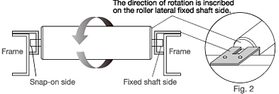
- To ensure contact of the product with the load, install it so that it is slightly above the idle roller surface (about 0.5 mm)
- Confirm that it is installed in a way to rotate in the right direction.
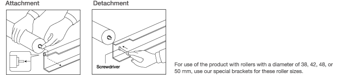
- For use of the product with rollers with a diameter of 38, 42, 48, or 50 mm, it is convenient to use our special brackets when installing it (Fig. 2).
Dimension and specification
A gap of 2 to 5 mm must be provided between the frame inside face and the product.
(The product is used with a gap of 5 mm as standard unless otherwise specified.)
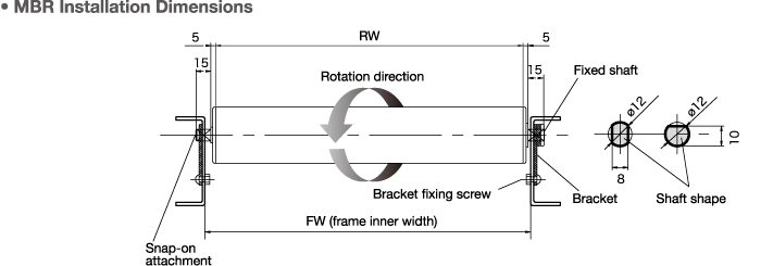
- The product (MBR) is intended to rotate in a predetermined direction. Please install it in a way to rotate in that direction (indicated on the side face of the product).
- Be sure to fix the supplied mounting brackets on the frame tightly at both ends of the product.
Use three mounting brackets (large, medium and small) for the shaft to be fixed and one mounting bracket for the snap-on shaft (slidable).
Operaton
Before starting operation, please carry out the following checks:
- Are the shafts of the product fixed with the supplied brackets tightly (three brackets on the fixed shaft side and one bracket on the snap-on side) ?
- Are the environmental requirements for the product met?
- Is the product in contact with the load?
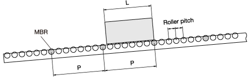
- Are the design installation conditions met?
MBR pitch P ≦ Load L + Idle roller pitch
- Do you have fail-safe measures against possible damages in case of a brake roller failure?
- For safety, if your current operating conditions are different from the conditions of which you initially informed us, be sure to let us know.
If a failure is suspected
Even if the product does not rotate or braking is too strong or too weak, in some cases it may not be a failure. Please carry out the following checks.
1) Is there a gap between the product and the frame?
2) Is the product rotating in the right direction?
3) Is the product in contact with the load?
4) Is the appropriate MBR model used?
5) Is the MBR (brake roller) pitch correct?
Contact
ASAHI KINZOKU Co.,Ltd.
140, Kodani, Hojo-cho, Kasai, Hyogo 675-2301 JAPAN
Phone +81-790-42-1214 / Fax.+81-790-42-0274
The information in this instruction manual is subject to change without notice.
Prior to ordering, please contact us for the latest information.