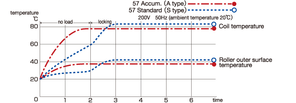
■ Locking Since a special motor is built in, the coil does not burn out even if the motor roller is locked for a short time. However, if it should be repeatedly locked, rise in the coil temperature and gradual deterioration of the insulation would occur, causing the motor to burn out. If locking continues 10 sec. or more, the user need not turn off the motor roller but it is advisable to de-energize it using a limit switch or relay. In this case, the accumulator type is more suitable.

The motor roller should be used within an ambient temperature range of -10 to 40°C. In normal operation, the temperature of the roller outer surface is 20°C higher than the ambient temperature.

Intermittent operation here means that motor rollers rotate and stop alternately as the power is turned on and off. Generally, in connection with coil temperature, the minimum cycle time for intermittent operation is as follows.

If the standard (S) type rollers are continuously used at a surface speed which is less than 60% of the one specified in this catalog, motor burnout would occur. For such an application, select the accumulator (A) type.
In order to avoid giving a strong impact to motor rollers, make sure that there is no serious speed difference within a line or in a joint between lines.
In selecting the motor roller model, take the following three factors into consideration:
Generally the tangential force required for conveyance is calculated from the formula below (depending on the weight, bottom size, material and flatness of the load).
F = μ・9.8W
where F: required tangential force (N)
W: weight of the load (g)
μ: coefficient of rolling friction of the load material
Coefficient of rolling friction of the load material (μ)

Determine the number of motor rollers by comparison between the required tangential force F and the tangential force per motor roller f. Required number of motor rollers: F ÷ f
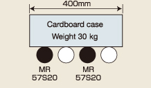
Select roller width 500, roller pitch 100 according to the shape and weight
of the load.
If the load’s weight W is 30 kg and the coefficient of rolling friction μ is
0.075, then the required tangential force for conveyance F is:
F = μ・9.8W =0.075 x 9.8 x 30 = 22.05 (N)
As a tangential force of 22.05 N is applied to the load, the rollers start conveying
it.
 When
3-phase 200 V (60Hz) power is used, one unit of any of standard models 57S4 to
57S25 is enough to start.
The load which one motor roller bears is:
30 kg ÷ 4 (rollers) = 7.5 kg.
This is within its allowable load range. Even if only one motor roller bears
the load, it is within the allowable range.
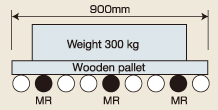
Select roller width 1000, roller pitch 100 according to the shape and weight
of the load.
If the load’s weight W is 300 kg and the coefficient of rolling friction μ is
0.035,
then the required tangential force for conveyance F is:
F = μ・9.8W =0.035 x 9.8 x 300 = 102.9 (N)
 When
3-phase 200 V (60Hz) power is used, one unit of any of standard models 57S4 to
57S6 is enough to start.
The load which one motor roller bears is:
300 kg ÷ 9 (rollers) = 33.3 kg.
Since the allowable load range for width 1000 is 50 kg, the motor roller can
bear the load.
This is the website of Asahi Kinzoku, a manufacturer known for its motor rollers.