■Wiring instructions

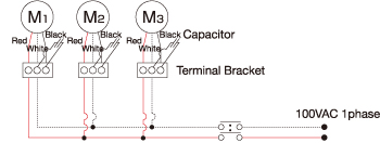
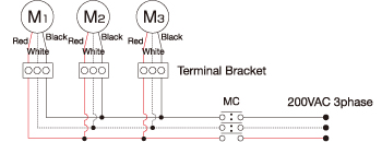
The motor roller has three power supply leads (red, white, black). The direction
of rotation can be altered by interchanging two of the three leads. When many
rollers are used and their leads are all connected in the same way, they rotate
in the same direction.
■Example of 100V single-phase wiring
(Capacitor installed outside)

■Example of 200V three-phase wiring

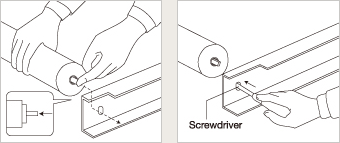
■Installation
The shaft end can be pushed in so that the roller can be easily fitted by
snap action.

■Anti-surge Measures
When the motor roller is turned on and off, a surge voltage (thousands of volts)
is generated momentarily.
Any surge voltage may unfavorably affect the motor coil and shorten the service
life of the motor roller.
To prevent this, use a noncontact relay to open or close the circuit or install
a surge absorber between the switch (magnet relay) and the motor roller.
■About the Use of an Inverter
An inverter cannot be used with any roller model intended to run on single-phase
power or on 380 V or more three-phase power.


